
 Breakdown of the PLC program workflow
To use the provided code, copy the Octalarm folders from both the Program Blocks and the PLC Data Types sections.
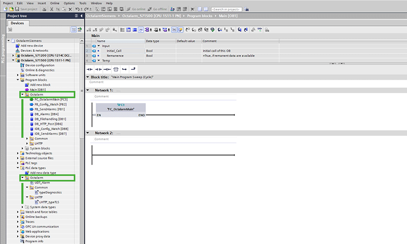
Call the function FC_OctalarmMain from your PLC’s main block. This function manages all tasks related to communication with the Octalarm system.
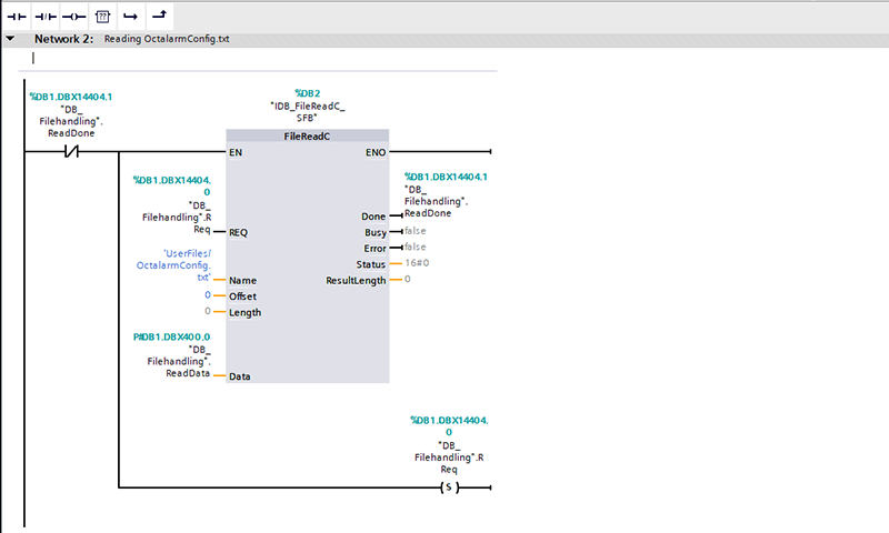
During the PLC’s initial scan cycle, the system reads the configuration file located on the memory card. The FileReadC instruction performs this action and continues to run until the process completes successfully. Once finished, the configuration data is loaded into a PLC data block and you no longer need to call the instruction.
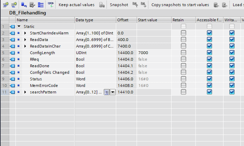
The array of bytes ReadData serves as the destination for configuration data read by the FileReadC instruction. You can adjust the array length to fit the configuration file size. If you modify the array sizes, update the initial value of ConfigLength accordingly to process the data correctly.
ReadData holds the ASCII codes of each character. Use the BYTE_TO_CHAR instruction to convert these codes into characters and store them in the same data block, specifically in the ReadDataInChar array.
Changing the configuration file
If the web server is enabled on the PLC and the user receives the correct rights for Filebrowser access, you can access the configuration file via a web browser. You can download, modify, and re-upload the file as necessary. This feature is useful for updating configuration data, such as adding a new location, category, or alarm, or changing existing parameters.
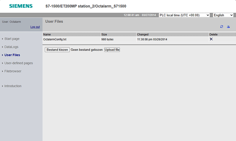
When you modify the configuration file, set the variable ConfigFileIsChanged in DB_Filehandling to true. This triggers the PLC to reread the configuration data from the memory card and update the relevant data blocks.
Function blocks with associated conditions
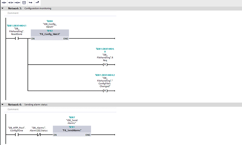
After reading the configuration data, the PLC calls two function blocks with their respective conditions:
FB_Config_Watchsends configuration data to the dialler and subsequently sends watchdog requests to monitor communication.FB_SendAlarmsmanages alarm status reporting to the dialler.
Both function blocks are implemented in SCL.
FB_Config_Watch
FB_Config_Watch uses an instance of LHTTP_POSTPUT_L. This instance first configures the dialler, then sends periodic watchdog requests.
In the Initiate state, the function prepares the data to be sent via HTTP POST by reading from the memory card. After sending the configuration data, it prepares and sends watchdog data at regular intervals to the dialler.
The flowchart below outlines the simplified operation of the FB_Config_Watch function block. It also shows the possible values for the StateMachine variable.
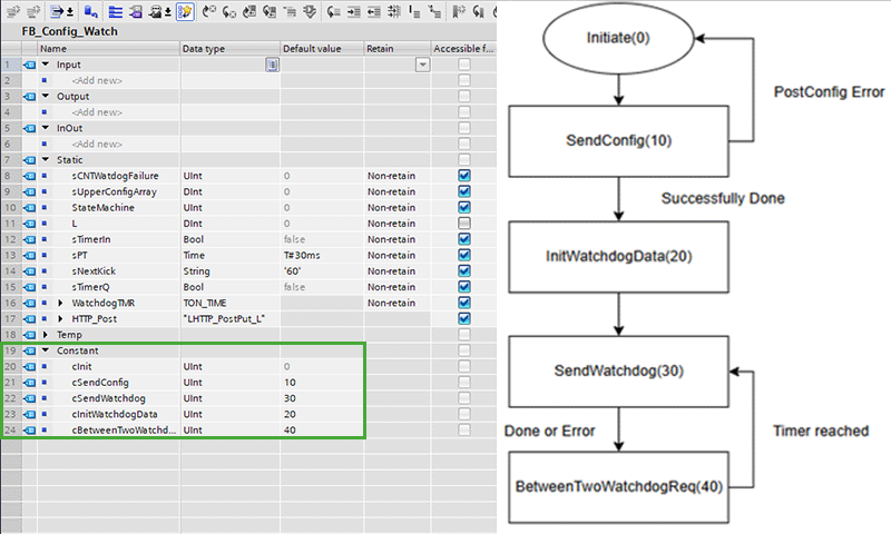
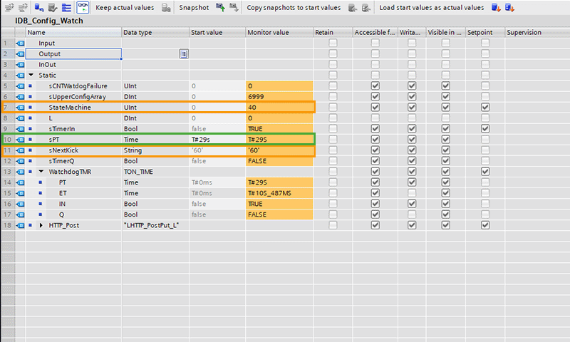
By default, the maximum interval between two watchdog requests is 60 seconds. The system attempts to send a request every 30 seconds. To modify these parameters, adjust IDB_Config_Watch accordingly.
To change the body of the watchdog API request, enter your desired string value in sNextKick and set the StateMachine to 20 (cInitWatchDogData) to apply your changes.
You can set the call interval for the watchtime API by adjusting sPT. This determines how often the PLC triggers the API call.
FB_SendAlarms

This data block contains an array of alarms:
Alarm[0]is reserved to indicate a communication failure.Alarms[1]toAlarms[Count](in our exampleAlarms[12]) represent the alarms defined in the configuration file.
To report the nth alarm from the configuration file, set DB_Alarms.Alarms[n] to true or false. The array index reflects the order in which alarms appear in the configuration file.
In UDT_Alarm, the status field shows the alarm’s current state, which the PLC programmer must update. The Status_Mem field stores the latest state sent to the dialler.
If the current status has changed and differs from Status_Mem, the PLC updates the Octalarm system accordingly. When this condition is met, the updated status is sent to the dialler using a POST request.