Quickstart Octalarm alarm diallers
Installation
Assembly
You can mount the Octalarm housing on a wall:
- Mount screws in the wall or panel.
- Slide the mounting holes of the device over the screws.
Note: Ensure the screws together can support at least 1,360 grams.
Connection
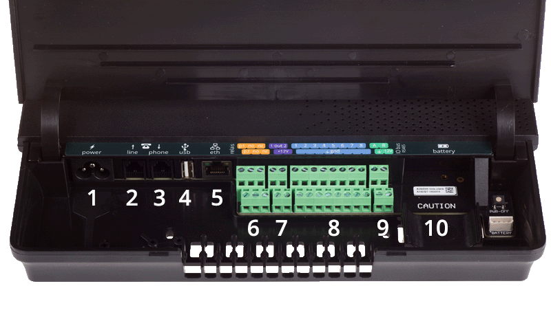
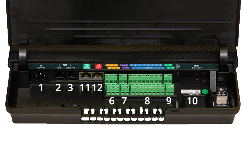
The connection sticker shows how to connect the various cables.
Connector sticker Touch

Connection sticker Touch Pro | ARA-Touch Pro

Description
| No. | Icon | Connection description | Touch | Touch Pro | ARA‑Touch Pro |
|---|---|---|---|---|---|
| 1 |  | Primary power supply (C5 connection) | ✔ | ✔ | ✔ |
| 2 |  | PSTN line in (RJ11) | ✔ | ✔ | ✔ |
| 3 |  | PSTN telephone (RJ11) | ✔ | ✔ | ✔ |
| 4 |  | USB port for service purposes | ✔ | ||
| 5 |  | Ethernet RJ45 | ✔ | ||
| 6 |  | Ethernet RJ45 | ✔ | ✔ | |
| 7 |  | Ethernet RJ45 | ✔ | ✔ | |
| 8 |  | Relay contacts | ✔ | ✔ | ✔ |
| 9 |  | Open-drain output | ✔ | ✔ | ✔ |
| 10 |  | Inputs | ✔ | ✔ | ✔ |
| 11 |  | RS485 data connection | ✔ | ✔ | ✔ |
| 12 |  | Connection for battery | ✔ | ✔ | ✔ |
Stable internet connection
A stable internet connection is required for reliable alerts.
Good to know: What to do with a firewall in the company network
Components explained
Screen
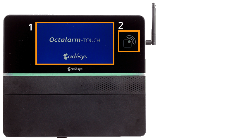
| No. | Icon | Description |
|---|---|---|
| 1 | Touchscreen | |
| 2 | RFID scanner |
Note: Do not use sharp objects on the touchscreen, as this may cause damage.
Power supply
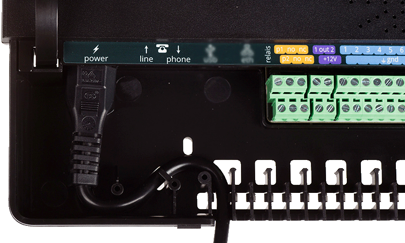
Insert the supplied power cable into the S-shaped holder to create a strain relief.
Note: The power cable must comply with IEC 60227-1.
Note: If you remove the power cable and battery abruptly, the system may, in rare cases, malfunction and stop working. Always shut down the dialler in a controlled manner.
Battery
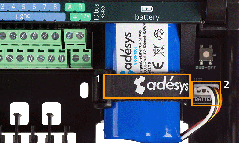
| No. | Description |
|---|---|
| 1 | Battery Velcro holder |
| 2 | Battery connection |
Note: Only use the official battery supplied by Adésys for the Octalarm alarm diallers (A-Batt-6.4V). This battery is fully approved and contains a chip to communicate its status with the system.
Good to know: With an undamaged battery, the alarm dialler operates for at least 30 minutes on battery power. In practice, this is often longer. Actual battery life depends on:
- The quality of the GSM 2G/4G signal. Poorer signals require more power.
- Whether an external buzzer and/or flashing light is connected.
- Whether an EM-8001 (external module) is connected and powered by the dialler.
Battery test
Test regularly whether the dialler continues to operate on battery power for at least 30 minutes by disconnecting the mains power.
Tip: Set the waiting time between replays for system failure network failure to at least 30 minutes. This prevents multiple system failure notifications if set shorter. See Alarms | Configuring inputs for more information.
PSTN configuration
You can connect the dialler to PSTN in 2 ways:
- Via a private PSTN line.
- Via a shared PSTN line with other equipment, such as a fax.
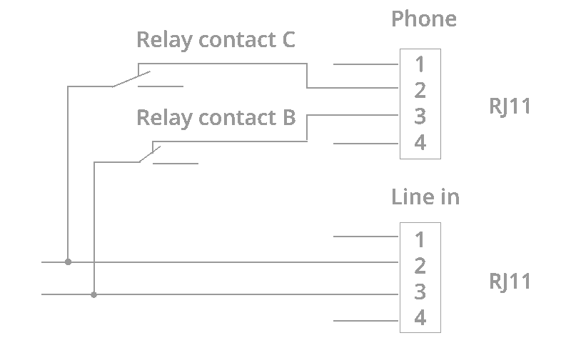
- In both cases, connect the PSTN line to the ‘Line’ (RJ11) jack.
- Connect any other devices to the ‘Phone’ (RJ11) jack.
This ensures the PSTN line is never busy for alarm notifications. However, due to a ‘Line-Seize’ relay, all other PSTN devices temporarily lose their connection during alarms.
Note: Test the operation of the ‘Line Seize’ relay immediately after installation and repeat this test periodically.
Antenna
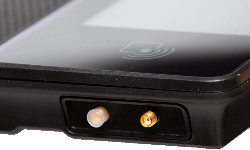
The alarm dialler has two antenna connections:
- The primary SMA connection (upper) is for both receiving and transmitting signals. Connect the required antenna to this socket. You can use the supplied antenna (AA-114).
- The secondary SMA connection (lower) is for amplifying the reception signal. In poor reception conditions, connect a diversity antenna as a second antenna to the lower SMA connection.
Good to know: Use the upper connection when using one antenna. Use the lower SMA socket ONLY to amplify reception via antenna diversity with a second antenna or an antenna with two sockets.
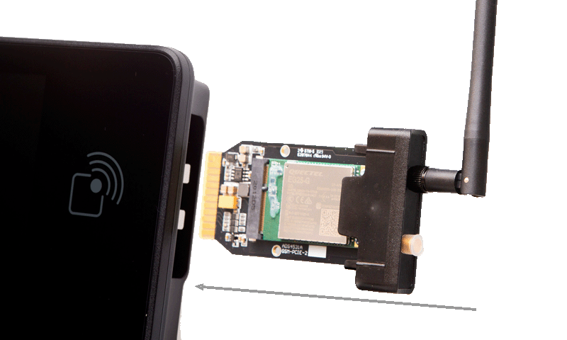
GSM module
Each dialler includes a GSM module with a non-activated SIM card. You can activate this SIM card during onboarding (when closing the Octalarm Connect service).
Inserting your own SIM card (format: mini-SIM)
Good to know: The SIM card format in the Octalarm alarm dialler is Mini-SIM (25 x 15 mm).
- Remove the GSM module from the dialler.

- Replace the SIM card on the back of the GSM module with your own SIM card (4G with LTE Cat-M1 band).
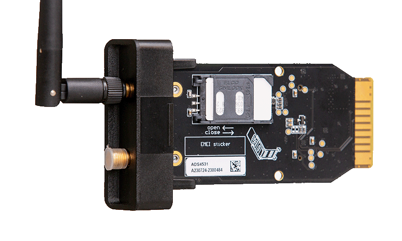
- Slide the module back into the GSM compartment until it clicks.
Labels
| Label | Description | Touch | ARA‑Touch Pro | |
|---|---|---|---|---|
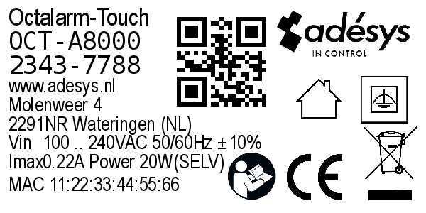 | Label housing, Europa (51x25mm) | ✔ | ||
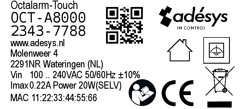 | Label packaging, Europa (71x36mm) | ✔ | ||
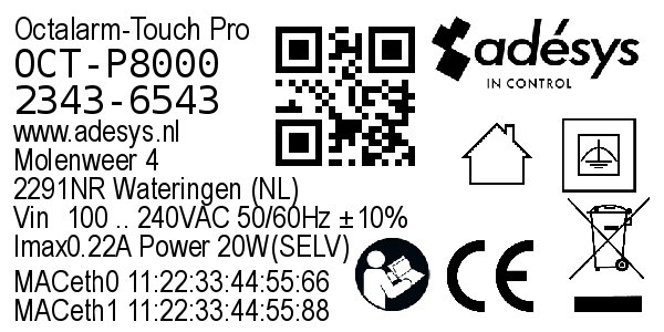 | Label housing, Europa (51x25mm) | ✔ | ✔ | |
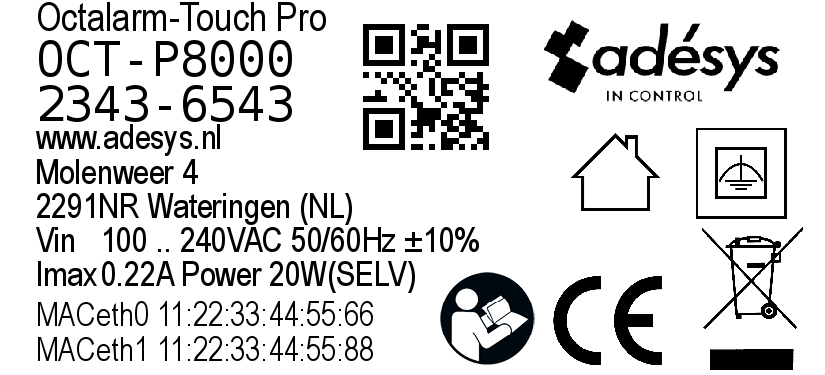 | Label packaging, Europa (71x36mm) | ✔ | ✔ | |
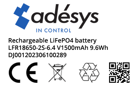 | Label battery (40x25mm) | ✔ | ✔ | ✔ |
Supplied accessories
| Image | Description | Touch | ARA | |
|---|---|---|---|---|
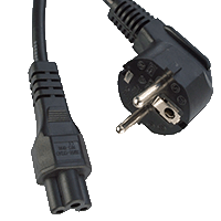 | Power cable Length: 1.5 metres Connector type: C5 Plug: EU-plug | ✔ | ✔ | ✔ |
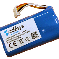 | Battery Rechargeable LiFePO4 battery LFR18650-2S 6.4 V/1500mAh 9.6WH | ✔ | ✔ | ✔ |
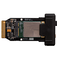 | GSM module LTE Cat. 4 (SIM card included) Note: the SIM card is not activated by default. You can activate it during installation and use it to close Octalarm Connect. | ✔ | ✔ | ✔ |
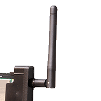 | Antenna SMA connector | ✔ | ✔ | ✔ |
 | Tag Quantity: 3 pieces Type: RFID 13.56MHz | ✔ | ✔ | ✔ |
 | Quickstart Installation manual | ✔ | ✔ | ✔ |