Quickstart EM-8001
Good to know:
- You need software version 2.1.1 or higher to connect 1 or 2 external modules.
- You need software version 2.7.1 or higher to connect 3 or 4 external modules.
Installation
Mounting
You can mount the EM-80011 on a wall or a 35 mm DIN rail.
Wall mounting
- Fix a screw in the wall or panel.
- Slide the module’s mounting opening over the screw.
DIN-rail (35 mm) mounting
- Place the top edge of the DIN rail section (on the back of the module) at an angle to the DIN rail.
- At the bottom of the module, release the clamping system and tilt the module until it is fully seated on the DIN rail.
- Click the clamping system into place.
Connection
Front view EM-8001
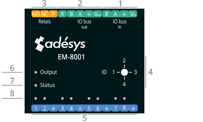
| Nr | Description front view |
|---|---|
| 1 | IO bus in |
| 2 | IO bus out |
| 3 | Relay contacts |
| 4 | ID (of the client) |
| 5 | Inputs |
| 6 to 8 | LED functionality |
LED functionality:
| Nr | LED | Colour | Status |
|---|---|---|---|
| 6 | Output | Green | Relay output active |
| 7 | Status | Green plus Red | Working Error |
| 8 | Inputs | Blue Green Red Orange | Confirmation of selected ID Alarm status: rest Alarm status: active alarm Alarm status: alarm accepted |
Client ID
The EM-8001 uses a master/client structure, with the Octalarm alarm dialler1 as the master and the EM-8001 as the client. If you connect multiple modules to an alarm dialler, assign a unique ID to each module.
- Use a screwdriver to set the ID on the module (see No. 4 in the front view).
- As you rotate the screw, the LED above the corresponding input number turns blue, indicating the selected ID.
Number of flashes at rest (idle):
| Number | ID |
|---|---|
| 1x | ID 1 |
| 2x | ID 2 |
| 3x | ID 3 |
| 4x | ID 4 |
Power supply
You can power the EM-8001 in 2 ways:
- from the Octalarm alarm dialler;
- with an external power supply.
Power supply from the Octalarm alarm dialler
- Use this option when:
- the dialler and external module(s) are mounted close to each other;
- you connect a maximum of 2 modules (up to 24 inputs).
- Use a 4-core cable with 2 pairs:
- Pair 1: signal line A and B;
- Pair 2: power supply and earth wire.
You can find the connections on the front sticker. See the wiring diagram for a graphical representation.
Note:
- If you use the relay, you must use an external power supply.
- You can power a maximum of 2 modules from the dialler. For 3 or more modules, use an external power supply.
- The power supply must be at least 15 VDC.
External power supply
- An external power supply is required for:
- long distances (> 100 meters);
- connecting the 3rd and 4th external module.
Good to know: for this, we supply the SV-20 (mains adapter) or the SV-24 (DIN-rail mounted power supply).
- Use a 3-core cable with one pair and one single core:
- Pair 1: signal lines A and B;
- Single core: ground wire.
The connections can be found on the front sticker. See the connection diagrams below for a graphical representation:
- 2x power supply from the Octalarm alarm dialler.
- 1x powered by the Octalarm alarm dialler and 1x via an external power supply.
- 2x powered by the Octalarm alarm dialler and 2x via an external power supply.
- 4x external power supply.
Note: with external power supply:
- The external power supply must be at least 15 VDC. Connect the external power supply to the V and earth terminals.
- Do not connect the power wire from the Octalarm alarm dialler to the EM-8001 when using an external power supply.
Signal lines for both power supplies
- Connect the wires as indicated on the front sticker.
- Terminate the last EM-8001 on the bus with a 120 ohm resistor. To do this, connect the ‘R’ and ‘B’ externally to each other on the screw connector.
Cabling
Always keep the wiring to the contact inputs as short as possible. If longer distances still need to be covered, this is best achieved by using a longer RS485 cable between the Octalarm and the external I/O module.
The Octalarm-Touch is certified for indoor use. This therefore also applies to the external I/O modules. If it is nevertheless unavoidable to route the cabling outdoors, the outdoor section must be fitted with surge protection at both ends, for example using surge suppressors.
See Technical Specifications EM-8001 for more detailed information about the cabling.
Examples wiring diagrams
Note: always enable the termination resistor on the last I/O module. To do this, connect R and B together.
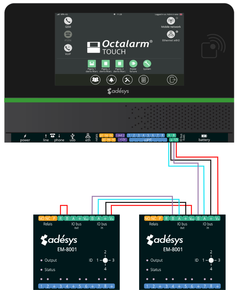
2x EM-8001 with power supply from the Octalarm alarm dialler
In this example, you connect two I/O modules to the Octalarm. Both modules are located close to the Octalarm alarm dialer, allowing them to be powered by the Octalarm.
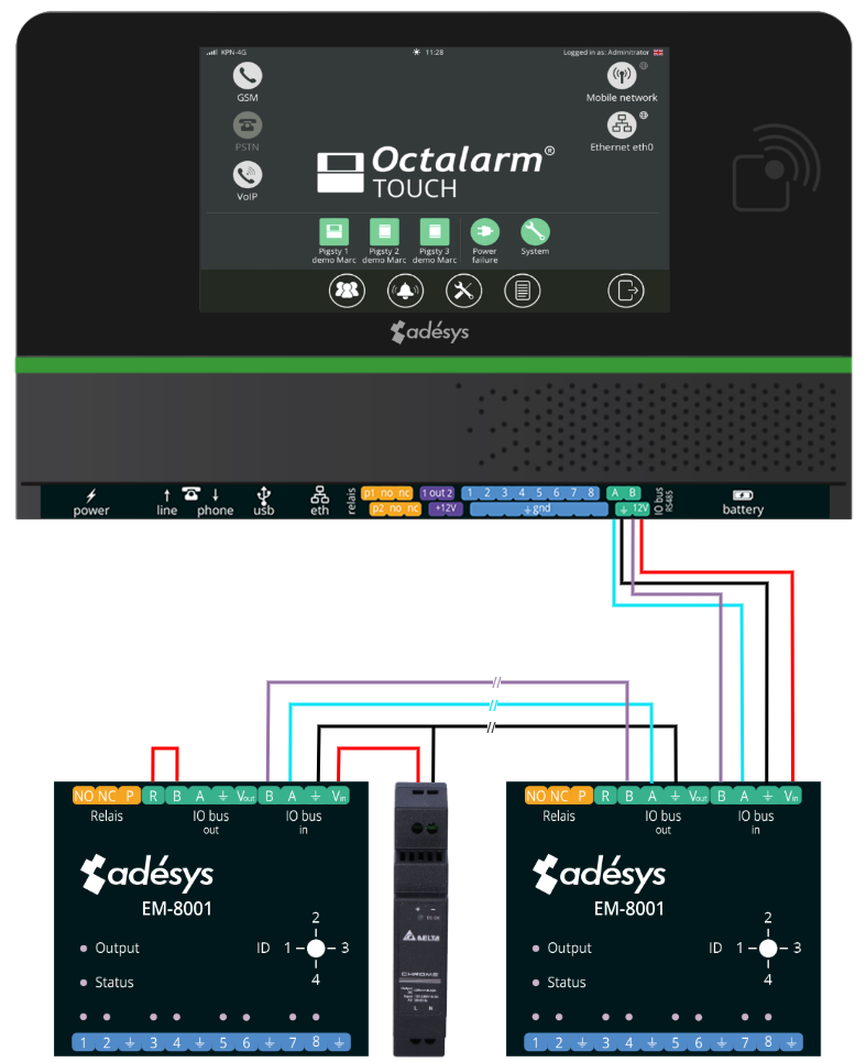
2x EM-8001, 1 is powered by the Octalarm alarm dialler and 1 via an external power supply
In this example, you connect two I/O modules to the Octalarm. One module is located close to the Octalarm alarm dialer and can be powered by the Octalarm. The other module is located more than 100 meters away; therefore, connect it to its own power supply.
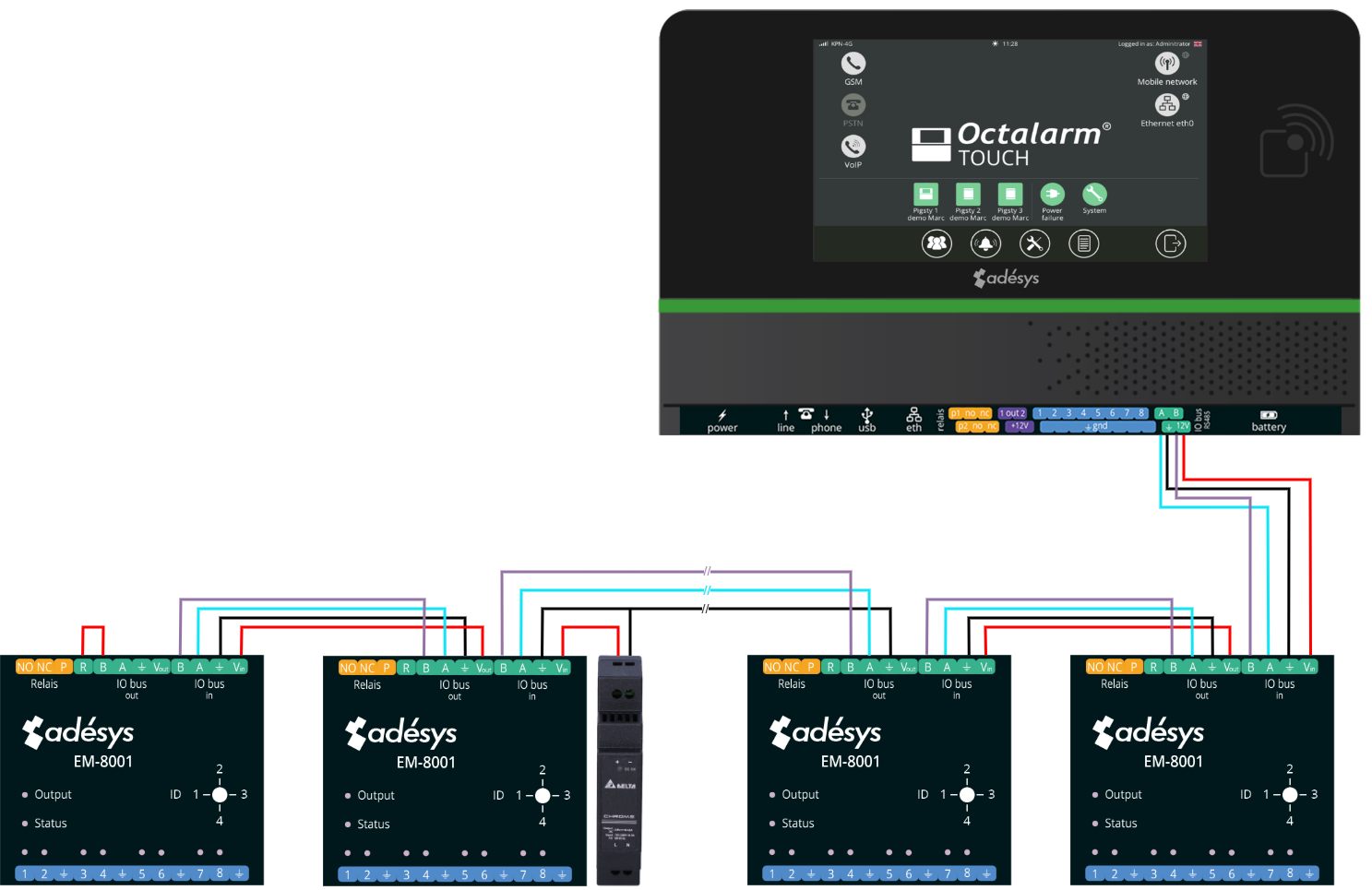
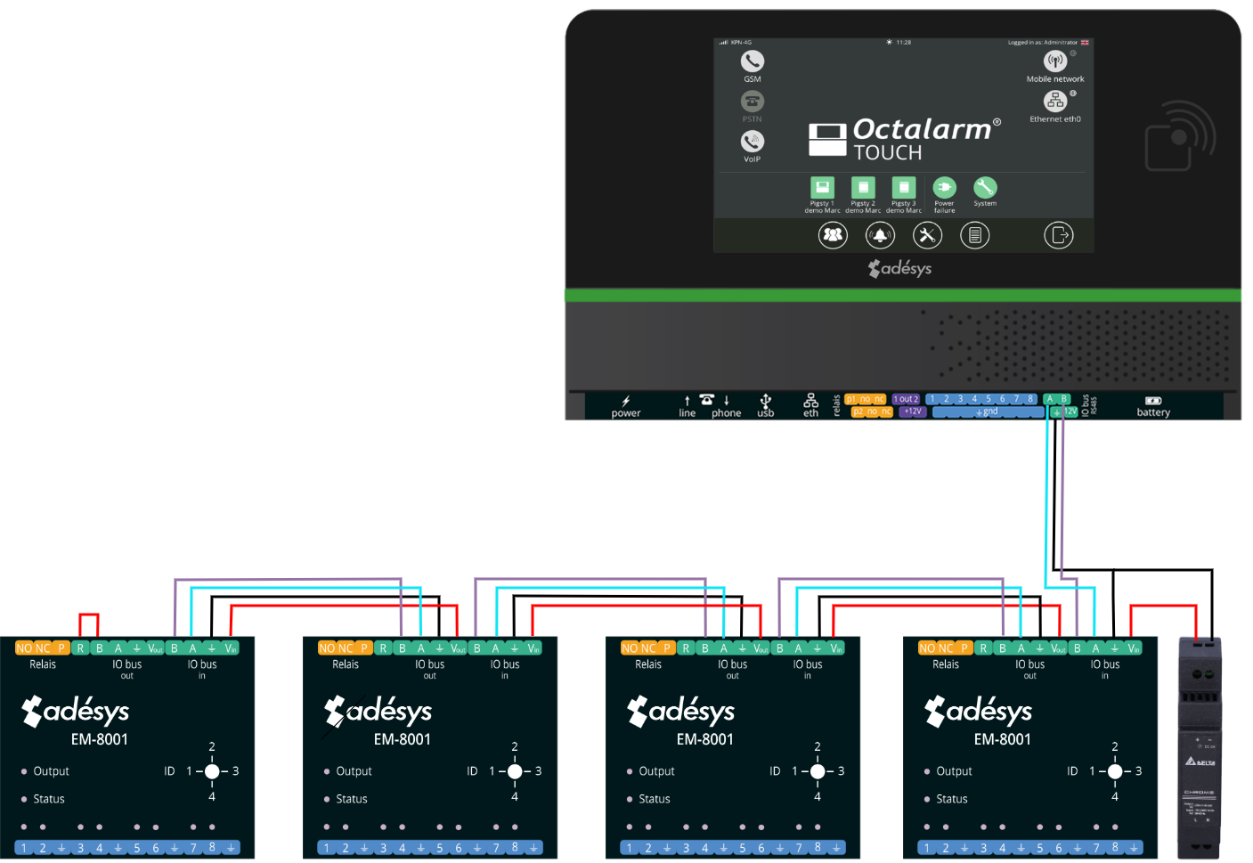
4x EM-8001, 2 are powered by the Octalarm alarm dialler and 2 via an external power supply
In this example, you connect four I/O modules to the Octalarm. When using more than two I/O modules, always use an external power supply. Two modules are located farther away and are therefore powered externally. The other two modules are located close to the Octalarm alarm dialer and can be powered by the Octalarm.
4x EM-8001 with external power supply
In this example, you connect four I/O modules to the Octalarm. When using more than two I/O modules, always use an external power supply. Since all modules are located farther away, all I/O modules are powered externally.
Labels
| Label | Description |
|---|---|
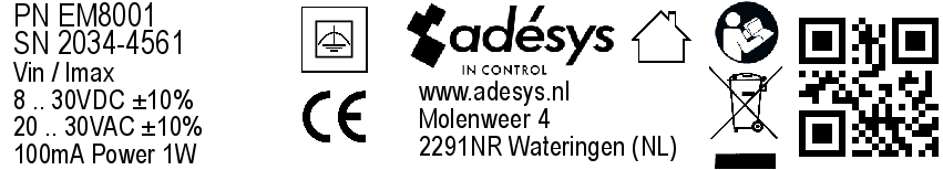 | Label housing (70x12mm) |